![]()
Accelerator
Control motor speed via a touchpad
What We Are Making
A motor which will spin based on
a speed reading from a soft touch pad.
Bits We Need
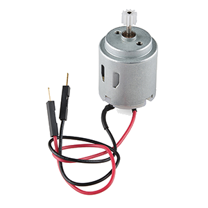
Motor
The visual output for our circuit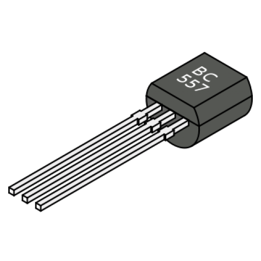
Transistor
To amplify the current to the motor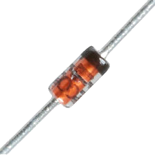
Diode
A one-way valve for the current
330Ω Resistor
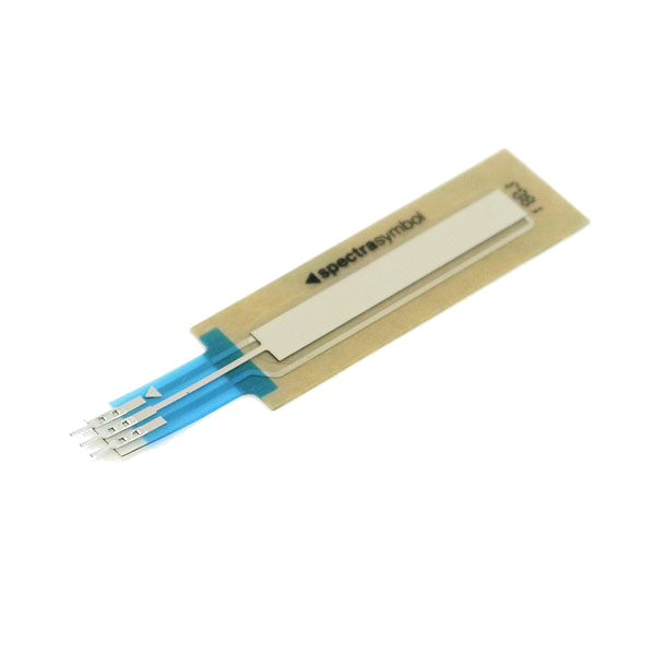
Soft Potentiometer
10k Resistor
Wires
To connect everything together!
Motor Overview
Setting up our motor will once again consist of two parts:
the physical components, and the logical components

Motor
The motor’s speed is determined by the voltage you put through it.
We send the motor an analog signal which is a number between 0 and 255.
The motor needs to be plugged into a digital pin which supports Pulse Width Modulation (PWM)
PWM allows us to send analog signals via a digital pin.
Transistor
Diode
Physical Components
of the Motor Circuit

Set up your motor as in the diagram.
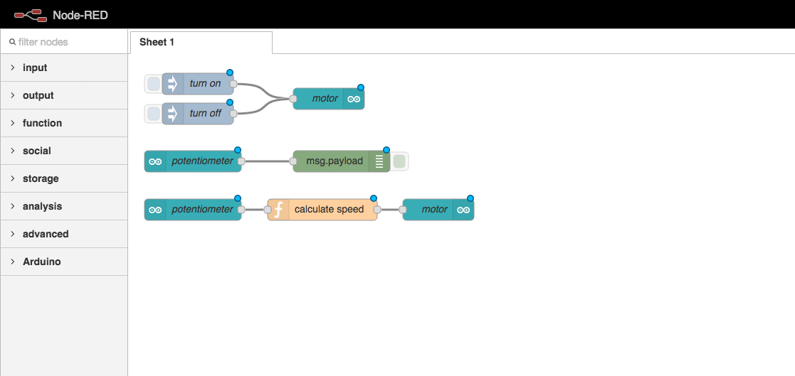
Logical Components
of the Motor Circuit

Test Buttons
One for “off” and one for “on”.
Arduino Output
Send the analog value to the motor.
Pass a Message Out to the Arduino
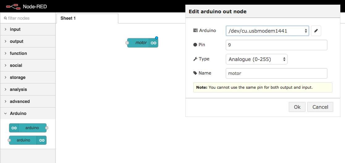
Drag an arduino out node into your workspace and configure it.
Inject a Message
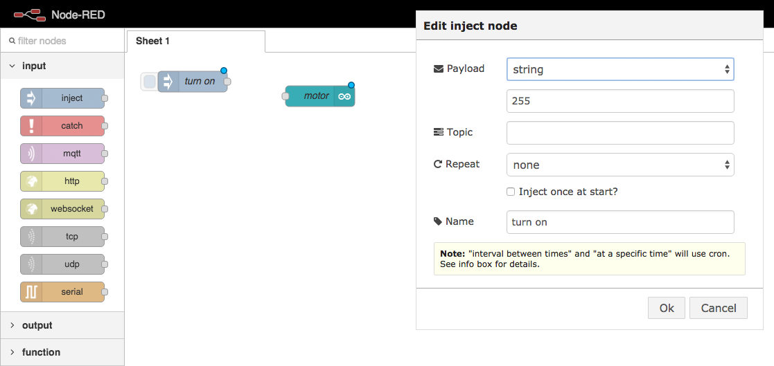
Drag an inject node into your workspace and configure it.
Inject a Message
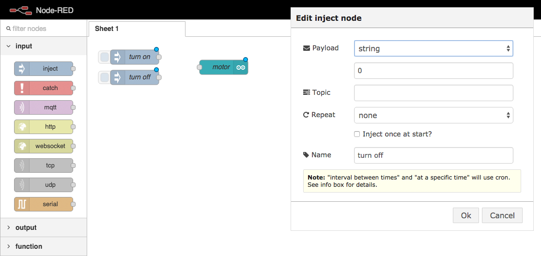
Drag an inject node into your workspace and configure it.
Connect the nodes
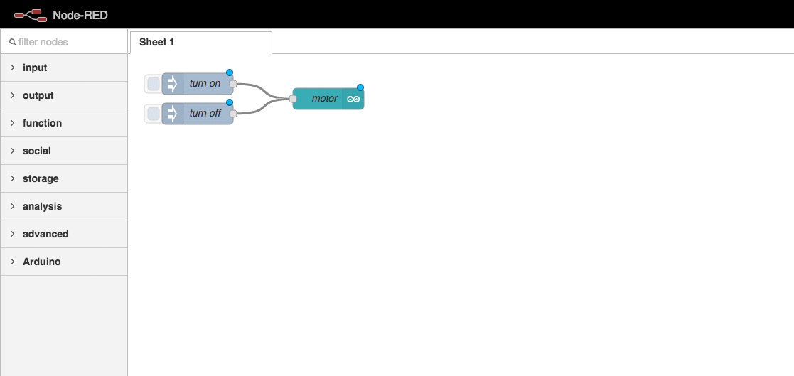
Click and drag the small square on the inject node,
and attach it to the arduino out node.
Deploy Your Code

Click the “Deploy” button in Node Red
to link your logic flow with the Arduino.
Test the Motor Output
The on-screen buttons should turn the motor on and off.
Potentiometer Overview
Setting up our potentiometer will also consist of two parts:
the physical components, and the logical components
Physical Components
of the Potentiometer Circuit

Set up your potentiometer as in the diagram.
Logical Components
of the Potentiometer Circuit

Potentiometer Input
Converts the Arduino signal
into a JavaScript message.
Debug Logger
Displays the JS message on
the screen when received.
Receive a Message from the Arduino
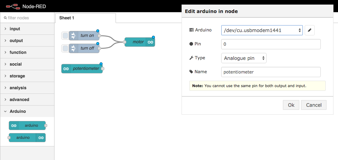
Drag an arduino in node into your workspace and configure it.
Debug the Incoming Data
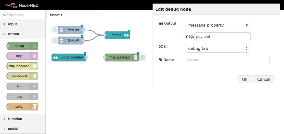
Drag a debug node into your workspace. The default configuration is fine.
Connect the nodes
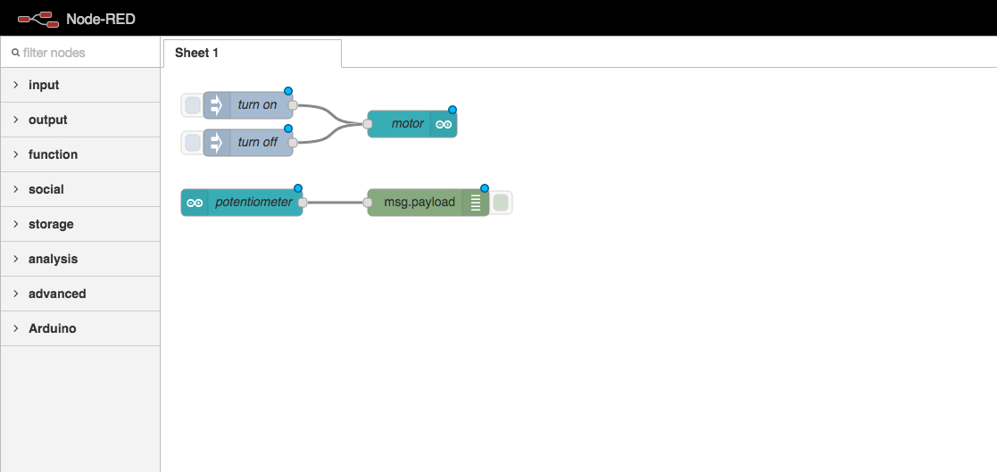
Join your arduino node to your debug node.
Deploy Your Code
Click the “Deploy” button in Node Red
to link your logic flow with the Arduino.
Test the potentiometer input
Turn the dial on your potentiometer.
You should see value being logged in your debug panel.
Logical Components
of the whole circuit
Potentiometer Input
Receives an Arduino signal
as a JavaScript message.
Conversion Function
Converts the potentiometer signal into the correct message for the LED.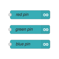
LED Outputs
Sends the JavaScript message
as an Arduino signal.
Circuit Arduino Nodes
Link your arduino input to the three arduino output nodes
via a function, like we did last time.
This time your function requires three outputs instead of one.
Function Code
var pressurePoint = msg.payload;
var lowestSpeed = 130;
var highestSpeed = 255;
var maxPoint = 1024;

if(pressurePoint < 100) {
    msg.payload = 0;
} else {
  var percentTotalSpeed = pressurePoint / maxPoint;
  var speedRange = highestSpeed - lowestSpeed;
  var speedAboveMin = percentTotalSpeed * speedRange;
  var finalSpeed = lowestSpeed + speedAboveMin;

  msg.payload = finalSpeed;
}

return msg;
Paste this code into your function config popup,
in the code editor section.
Shorter Function Code
// mapping function
getSpeed = function(currentPressure) {
  var pressureMax = 1024;
  var motorMin = 130;
  var motorMax = 255;
  var speed = currentPressure * (motorMax - motorMin) / pressureMax + motorMin;

  return speed;
}

msg.payload = (msg.payload > 100) ? getSpeed(msg.payload) : 0;

return msg;
For experienced coders:
This code does exactly the same thing,
but is a bit shorter.
Deploy Your Code
Click the “Deploy” button in Node Red
to link your logic flow with the Arduino.
Full Circuit Test
Press different points on the soft potentiometer.
Your motor should spin at different speeds.

Accelerator: Complete!
Well done :) That’s everything!
Loading...