![]()
Binary Blink
Light on, light off.

What We Are Making
Turn a light on and off by pushing a button.
Bits We Need

LED
A visual output for our circuit
Button
An input, used to turn our light on and off
10k Resistor
To regulate the voltage readings from the button
Wires
To connect everything together!
LED Overview
Setting up our LED will consist of two parts:
the physical components, and the logical components
Physical Components
of the LED Circuit

Set up your LED as in the diagram.
Logical Components
of the LED Circuit
Test Button
On-screen button, sends message
that light should turn on.
Light Output
Converts test button message
into an Arduino signal.
Pass a Message Out to the Arduino
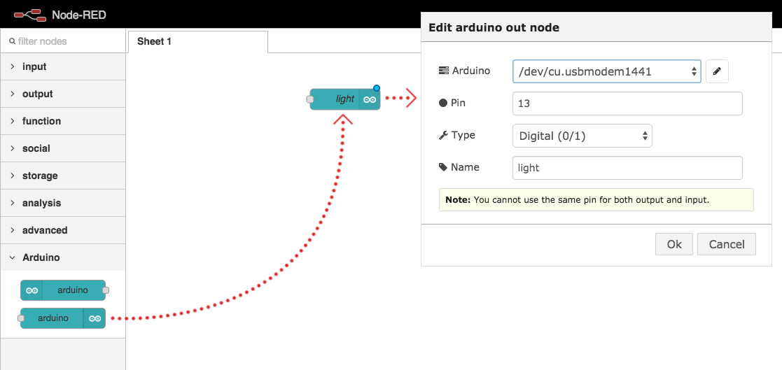
Drag an arduino out node into your workspace and configure it.
Inject a Message
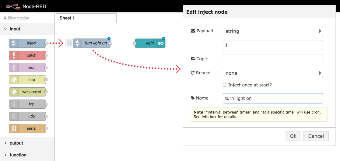
Drag an inject node into your workspace and configure it.
Connect the nodes
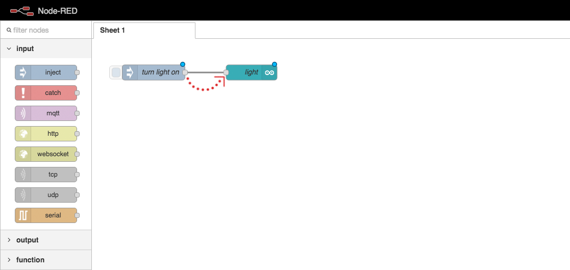
Click and drag the small square on the inject node,
and attach it to the arduino out node.
Deploy Your Code

Click the “Deploy” button in Node Red
to link your logic flow with the Arduino.
Test the LED Output
Click the square trigger button on the inject node.
Your LED should turn on and stay on.
Physical Components
of the Button Circuit

Set up your button as in the diagram.
Logical Components
of the Button Circuit
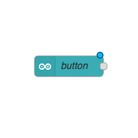
Button Input
Converts the Arduino signal
into a JavaScript message.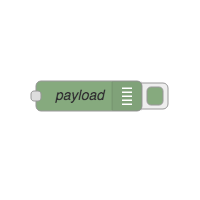
Debug Logger
Displays the JS message on
the screen when received.
Receive a Message from the Arduino
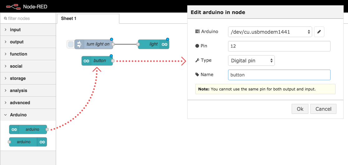
Drag an arduino in node into your workspace and configure it.
Debug the Incoming Data
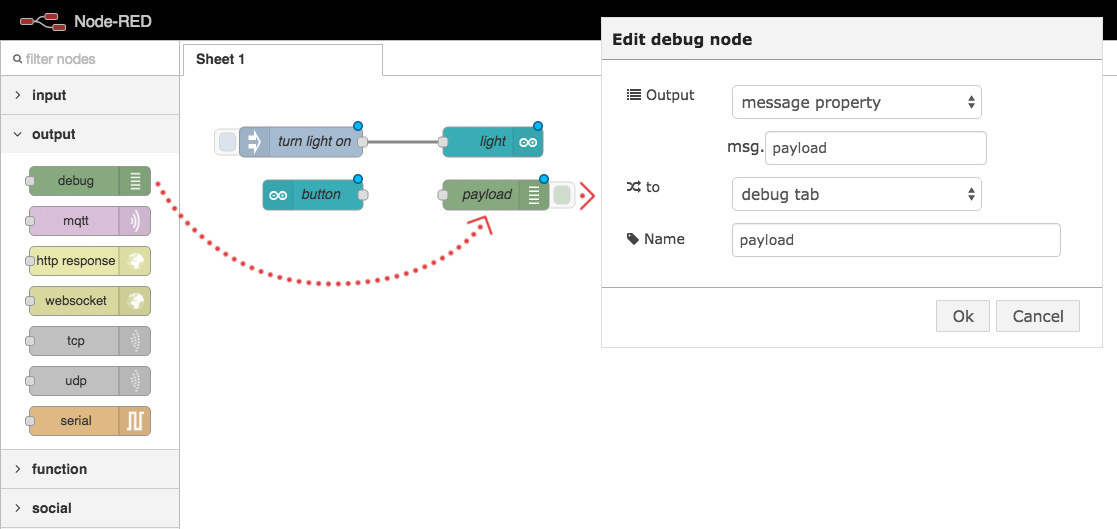
Drag a debug node into your workspace and configure it.
Connect the nodes
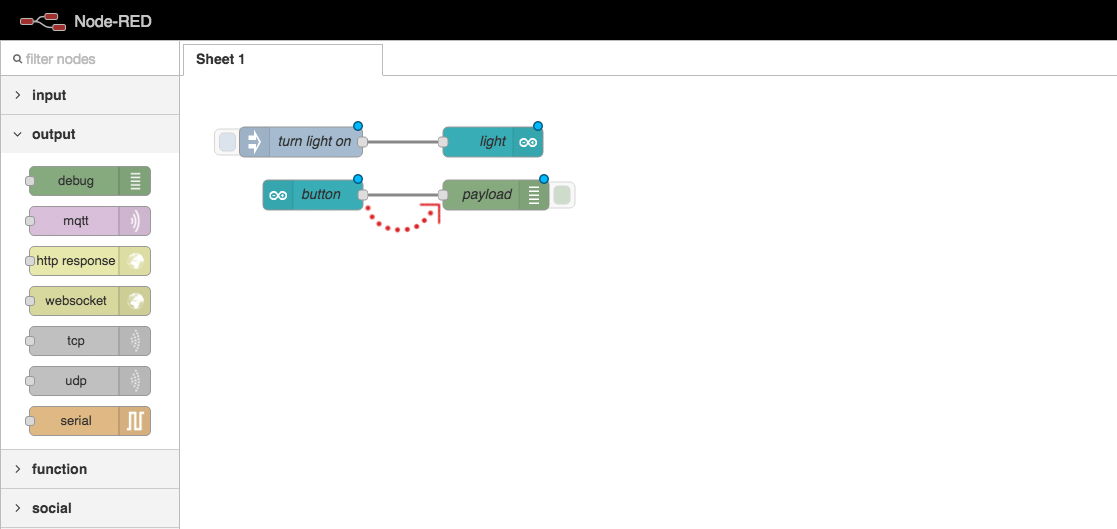
Click and drag the small square on the arduino node,
and attach it to the debug node.
Deploy Your Code
Click the “Deploy” button in Node Red
to link your logic flow with the Arduino.
Logical Components
of the whole circuit
Button Input
Receives an Arduino signal
as a JavaScript message.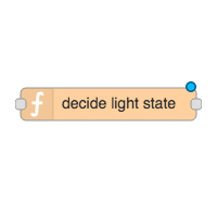
Conversion Function
Converts the button signal
into the correct message
for the LED.
LED Output
Sends the JavaScript message
as an Arduino signal.
Circuit Arduino Nodes
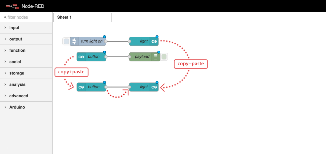
Link the Arduino input and output directly.
The LED should be on when the button is pressed down.
Conversion Function
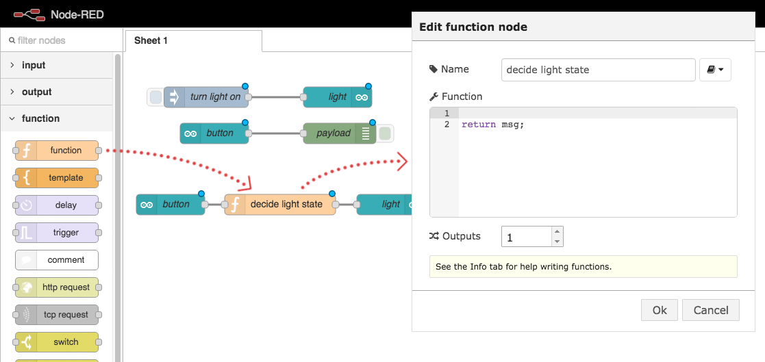
Link a function between the in node and the out node,
so we can manipulate the value being passed along.
Function Code
var buttonPressed = msg.payload;
var lightOn = context.lightOn;

if(lightOn === undefined) {
    lightOn = false;
}

if(buttonPressed === true) {
    if(lightOn === true) {
      lightOn = false;
    } else {
      lightOn = true;
    }
}

context.lightOn = lightOn;
msg.payload = lightOn;

return msg;
Paste this code into your function config popup,
in the code editor section.
Shorter Function Code
var buttonPressed = msg.payload;
var lightOn = context.lightOn || false;

if(buttonPressed) {
    lightOn = !lightOn;
}

context.lightOn = lightOn;
msg.payload = lightOn;

return msg;
For experienced coders:
This code does exactly the same thing,
but is a bit shorter.
Deploy Your Code
Click the “Deploy” button in Node Red
to link your logic flow with the Arduino.
Test your circuit
Your button should now act like an on/off switch

Challenge: Stop and Go
Add a green LED to your circuit to make a stop/go light.

Binary Blink: Complete!
Cool, now let’s try something a little more complex…
Loading...